Android 11
After some years, I have decided to make another android project. This one will be much smaller than my previous projects, which were up to 5 feet tall, and will therefore enable me to make something that works more effectively that I can get stuck into programming more quickly.
This project is ‘Android 11’
This page will be updated as I make progress, with the newest updates at the top. Click the pictures for bigger versions.
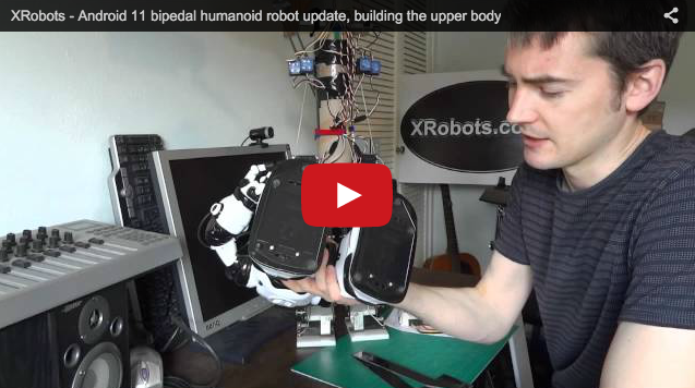
17th November 2012
I have made an update video of this demonstrating operation with the upper body installed. There are some pictures below of the details:


13th April 2012
Here’s the continuation of the upper body, and also a YouTube video of me making and talking.


11th April 2012
I’ve finally started on the upper body of the android – this part will allow weight to be shifted backwards or forwards to help with walking. Currently the android is a bit unstable in this axis. The upper body will hinge at the waist and have the batteries and power regulator mounted on it. Here is the start of the pieces, and a YouTube video about the plan/construction.


10th December 2011
It’s been a while since I’ve provided an update on this, mostly because I’ve been playing around a lot with some piezo gyros to make the android dynamically stable. These are heading gyros intended for use with radio controlled helicopters which are wired inline with a servo, so as you rotate them through space they offset the servo position. They also have an input for sensitivity which connects to another servo channel so you can adjust the magnitude of the offset.


I have four of these gyros attached to the android, each one deals with one servo for the side-to-side movement at the hips and ankles. The next step is to make a front-to-back joint above the hips with another gyro to take care of this.
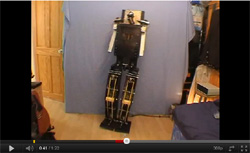
As you can also see, I’ve added a temporary body to the android made from a cardboard tube, with most of the weight on the top of it including the batteries. This means I can see how it will move once I’ve actually built the top half, and it makes quite a difference to the dynamics overall. The android now stands about 70cm tall.
The gyros can be set so that they are sensitive enough that the android naturally oscillates, all the time trying to remain upright. The same gyro sensitivity is also used for a basic walking sequence – where the microcontroller moves all the servos on fixed timers and to fixed positions, allowing the gyros to compensate as needed so the android doesn’t build up momentum and topple. This is all still under the control of a single Picaxe-18X microcontroller.
Here’s a quick video of the Android in action as described above:

8th October 2011
I’ve temporarily added the battery and electronics, from my first post on this project, to the android. I’m using a small power regulator board I got from eBay to give me 6v for the servos, and a 5v regulator to drive the electronics, all fed from a Li-ion 12v battery pack.
The android is capable of a walking and can position itself to stand onto either leg. The next step is to split the hips to allow each leg to rotate so it can turn on the spot on walk in a circle, and then I’ll build the rest of the body.


30th September 2011
My servos arrived, so I’ve fitted eight of them to the android and made a piece for the hip assembly, although this piece will eventually be split to allow the legs to rotate. The android is currently 40cm tall at it’s highest point, Initial tests indicate that the servos are more than strong enough for it to work since there’s quite a lot of leverage in the mechanism.
The next step is to fit the electronics on board, tidy up the cables and program it to do some simple things.


24th September 2011
I’m still waiting for the servos to arrive, which is where the main delay is. However, I’ve worked on the ankles and feet of the android, allowing space for a servo to lay flat on the top of each foot to deal with the side to side leaning motion. There are still a few adjustments to make, but I really want to have the actual servos before I make any commitments to their fittings etc.


17th September 2011
I’ve worked some more on the construction of the legs which are now made from various materials, including HIPS, HDPE, and Aluminium:


I’m waiting for the twelve servos to arrive before I put the legs together properly, there will be two servos in each half of the leg and that leaves four for extra functions.
11th September 2011
I’ve started to make some of the leg pieces for Android 11, these are cut out from 2mm HIPS plastic sheet with a knife, which isn’t very high tech.


These parts are very similar to, and based entirely on Android 6, but five times smaller. I have some servos due to arrive shortly, so I can’t cut the servo moulding brackets until they get here.
9th September 2011
Android 11 will work in a very similar way to some of the previous android projects, it will be based on Android 7 and Android 6, although on a smaller scale with a higher motor count for better control. Here are some videos of the previous Androids in action:


Android 11 will be around 18″ / 45cm tall and it will use r/c style servos to drive the joints. These will be much easier to control than the horrendous electronics I built to control the auto wiper motors used in the previous larger androids.
The basic principle of how the legs work is demonstrated by the Lego model below. Looking sideways, each half of the joint is a parallelogram which means that no matter what the pose is, the torso will also remain bolt upright. This makes programming much easier because there is less overall influence on stability by moving one motor at a time, which would otherwise have an impact on the position of the balance on both legs.
For instance, if the android had separate ankle, knee and hip joints, then moving any one of them would rotate the torso away from being perpendicular to the ground, and also change the angle of the other leg relative to the ground, unless compensation was made by other joints simultaneously. Doing it this way also reduces the motor count by one, because only two instead of three motors are required per leg in this plane.


Looking from the front, Android 11 will have one motor per ankle and one motor per hip in order to shift it’s weigh over each foot. Androids 6 and 7 had no ankle motors in this plane due to weight considerations, which made them quite unstable – they relied on end stops for the joints and some bungee cord to keep them upright.
To start with Android 11 will be statically stable – so it’ll move slowly enough not to build up momentum and over balance. Once that works I’ll experiment with a small solid state gyro, which will likely be attached to a servo driving a hinge above the waist which controls the angle of the entire torso to keep balance when walking quickly.
Android 11 will be constructed mostly from sheet plastic material, nuts & bolts etc. The legs will be very similar in style to Android 6, having parallel sheet sections with the motors mounted inside the top and bottom of the legs. I may also make some custom plastic pieces for some of the more complicated mechanical parts by scratch building them from something, making silicone moulds, and casting them in polyurethane plastic.
The electronics for controlling the servos will initially be very simple. I’ll be using a Picaxe for the main microcontroller for now, and a Pololu Maestro servo controller to control the servos. This servo controller takes TTL level serial commands at 4800 baud from the Picaxe and has the capability to set speed and acceleration of each servo as well as position, so this means I can easily make smooth servo movements which ramp up and down in velocity as they change position.

Here’s my simple test setup using the Picaxe 18 project board and the Pololu Maestro controller. To drive the Pololu servo controller from the Picaxe, you need to do the following:
-Plug the Pololu controller into your computer with a USB cable and use the Pololu software to set the serial baud rate to 4800 (or 2400 baud if you’re using a slower Picaxe).
-Set the range of the servos to move as far as you’d like them to – I had to make the range quite a bit larger to get 180 degrees of movement from them.
-Use the following code to drive the servos as required. Note that if you’re using a Picaxe output directly you will need to use T for true serial, but if you’re using a project board that has a darlington array on then you’ll need to use N for inverted serial because the darlington driver inverts the signal. (mine actually uses N but the examples below show T to match the Pololu documentation.
To set acceleration: This example used pin 0 of the Picaxe at 4800 baud. 137 is the parameter for acceleration, 0 is the servo channel number, 6 is the acceleration value (low bits), and 0 is the acceleration value (high bits).
serout 0,T4800,(137, 0, 6, 0)
To position the servo: This example used pin 0 of the Picaxe at 4800 baud. 255 is the parameter for driving the position, 0 is the servo channel number, and 127 is the position – which is about in the middle.
serout 0,T4800,(255, 0, 127)
I’m also using the Picaxe official infra red remote control kit so I have an easy method of triggering the Picaxe when testing. This means I can program various routines and then trigger them from buttons on the remote.
I will be making a YouTube video about this soon showing my servos etc in action.
Related Posts


About The Author
James Bruton
My name is James Bruton, I live in Southampton, UK. Please note that this is my personal project website, I have no products for sale, most of the information is provided so that you can have a go yourself... Read More